Uncloaking Radio Frequency Identification (RFID)
Demystify RFID with insights on components, tag types, modulation, and use cases. A concise guide to the intricate world of RFID.

Demystify RFID with insights on components, tag types, modulation, and use cases. A concise guide to the intricate world of RFID.

Radio Frequency Identification (RFID) is used as an identification method through radio waves via the air interface. There are several components required to make RFID work.
The hardware summarizes as the RFID tag (also known as transponder), the RFID reader (also known as interrogator), an antenna and a power supply for an RFID system.
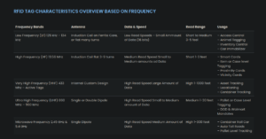
RFID within the 125-134 KHz (LF) and 13.56 MHz (HF) frequencies operate in near-field where as 100MHz (such as Very High Frequency 433MHz and Ultra High Frequency 860-960 MHz) operate in far-field.
source: https://rfid4u.com/inductive-and-backscatter-coupling/
Virtually all systems that use RFID for monetary transactions operate at 13.56 MHz. This makes sense as Near-Field Communication (NFC) was adopted for payment and other applications and uses 13.56 MHz as well.
source: https://www.rfidjournal.com/question/what-are-the-typical-rfid-tag-frequencies
Security research tools such as the Proxmark3 support the 125-135 KHz and 13.56 MHz frequencies. This might be for the reason that a lot of access controls, smart cards etc. communicate on these frequencies (see image below).
There exist different tags in RFID used for different use cases: passive, semi-passive and active tags.
For offensive security operations – also depended on the engagement – it seems to be more probable to encounter passive than active tags, due to the varying use cases. It is really depended on the client though.
Passive tags typically operate in low frequencies (125KHz – 134KHz), high frequencies (13.56MHz) and ultra high frequencies (860 to 956 MHz).
source: https://www.rfidjournal.com/question/what-are-the-typical-rfid-tag-frequencies
A passive tag gets its power from the reader through an electromagnetic field. Once it receives power it will transfer its data to the reader, which can detect the presence of the passive tag through changes in the current flow. The changes of the current flow are achieved by the passive tag through load modulation. More on modulation later.
source: https://home.cs.colorado.edu/~rhan/CSCI_7143_001_Fall_2002/Papers/rfid_intro_01593568.pdf
Some of their use cases are access control, animal tagging, inventory control, car immobilizer, smart cards, item of case level tracking, proximity cards and vicinity cards (see image above).
https://www.computype.com/blog/rfid-and-the-difference-in-passive-semi-passive-and-active-tags/
Also referred to as Battery-Assisted Passive (BAP) or Battery-Assisted Tags (BATs). They have no transmitter on board (which would require a lot more electronics and power, making the tag bigger, heavier and more expensive), meaning it is required to receive a signal from the interrogator first to modulate its data onto the carrier wave for back scattering. The tag however, in comparison to a passive tag, is not required for power supply by the interrogator due to its on-board battery.
As the tag uses back scattering and does not require inductive coupling as a power supply, it allows for a longer read range (30+ meters) than a standard passive tag, while also allowing for the possibility of onboard (environmental) sensors.
Example sensors for a semi-passive (or active tag) would be temperature, pressure, relative humidity, acceleration, vibration, motion, altitude, and chemical sensors.
source: https://rfid4u.com/rfid-passive-active/
Semi-Passive tags operate in ultra high frequency such as 860-960MHz and microwave frequency (not an extensive listing). This also makes them use back scattering over inductive coupling, due to the range these tags communicate with.
source: https://rfid4u.com/rfid-frequency/
Some of the areas semi-passive RFID tags are used are pallet or case level taggig, DOD & walmart mandates, container rail car, auto toll roads and pallet level tracking (see image above).
Active tags use 433 MHz and higher frequencies such as 2.45 GHz and 5.6 GHz. They have their own power source and thus do not require the induction of the reader used to generate power for the passive tags.
source: https://www.rfidjournal.com/question/what-are-the-typical-rfid-tag-frequencies
Active RFID tags differentiate as transponders and beacons. Transponders only communicate when they are in the surrounding and presence of a reader. Beacons constantly broadcast their signal.
source: https://www.techtarget.com/iotagenda/definition/active-RFID-active-radio-frequency-identification
Some of the active RFID tag use cases are asset tracking, locationing, container tracking, pallet or case level tagging, DOD & Walmart mandates, container rail car, auto toll roads and pallet level tracking (see image above).
Passive readers require to be ‘awoken’ by the active tag. This also means that the tag needs to have a transmitter on it, so it can send a signal by itself and is not required to be powered by the reader.
A active reader in combination with a passive tag needs to supply power to the tag so it can send data back to the reader.
An active reader uses an interrogator signal to activate the active tag. This setup could also be a variation of a BAP (battery assisted passive).
source: https://en.wikipedia.org/wiki/Radio-frequency_identification
Coupling is the process of transferring energy from one to another medium. The coupling used depends on the frequency and distance.
Near-Field RFID uses induction for power coupling from the reader to the tag and load modulation to transfer the data from the tag to the reader.
Inductive Coupling
Inductive coupling enables the active reader to power the passive tag (in an ARPT setup). This is done through the creation of a shared magnetic field, where changes of the current flow in one device, induces changes of the flow in another device.
RFID systems operating in the frequency 125-135kHz and 13.56 MHz use inductive coupling. The 13.56 MHz near-field zone ends in 3.5 meters and due to that the read range is typically 1m (depending on the antenna of the reader).
To transfer data from the passive tag to the active reader load modulation is used while the induction allows for power coupling from the reader to the tag. The tag communicates with the interregator by switching the load of the antenna rapidly on and off. This can be detected by the reader and thus can interpret the changes as data transmitted from the tag.
Since inductive coupling operates in the near-field any interference from other systems are lower (in comparison to far-field communication through backscattering). Furthermore, the communication is not affected by human tissue or water but by metal.
source: https://rfid4u.com/inductive-and-backscatter-coupling/
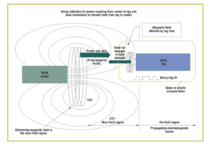
image source: https://home.cs.colorado.edu/~rhan/CSCI_7143_001_Fall_2002/Papers/rfid_intro_01593568.pdf
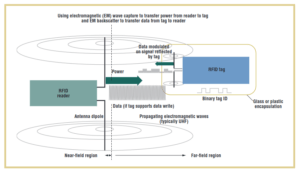
Backscatter Coupling
With backscatter coupling the carrier signal from the interrogator is used to transfer the data from the tag to the reader. The carrier wave that reaches the tag, supplies power to it, is modulated with the data stream and reflected to the reader.
The modulation is done by switching the load resistor that is connected in parallel to the antenna rapidly on and off in time with the actual data stream. The rapid changes, influence the resonant properties of the antenna making it a poor or good reflector, producing different strength in the signal. The created pattern (data), by using this technique, is what is being reflected and will be received by the reader which then detects the data stream.
source:
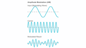
To understand modulation, the basic properties of electromagnetic waves are important. Each of these properties can be used to achieve a different type of modulation:
The carrier wave does not hold much information and is a pure wave of constant frequency.
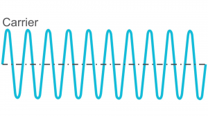
The input signal or modulated wave carries the actual information and is ‘put on’ to the carrier wave to transmit the actual data. By modulating the input signal onto the carrier wave we change the shape of the carrier signal and thus ‘encoding’ the data stream on it.
The modulation itself can be achieved through different techniques
The modulated result (also called modulation scheme) is created by modulating the input signal or modulation wave onto the carrier wave. This creates the actual wave that is being transmitted and also called modulated result.
Amplitude Modulation (AM) takes an input signal and uses it to change the height of the carrier wave. This happens if the input signal contains different heights (an example would be speech and the loudness of the speech), which then will change (by modulation) the height of the carrier wave or at this stage the modulated result.
Frequency or the number of waves per second, can also be used to modulate the carrier wave with the desired information. If the modulated wave has another frequency than the carrier wave and is being modulated with it, it will lead to a modulated result with varying frequency, creating the data stream.
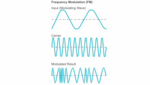
source: https://www.taitradioacademy.com/topic/how-does-modulation-work-1-1/
In digital modulation the data is turned into a bit-stream of ones and zeros. This data then will be modulated on the carrier wave and transmitted over an analog communication channel. Some techniques are
source and further reading: https://www.electronicdesign.com/technologies/communications/article/21798737/electronic-design-understanding-modern-digital-modulation-techniques
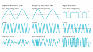
image source: https://www.taitradioacademy.com/topic/how-does-modulation-work-1-1/
In this article we covered how an RFID system is setup. We explained the different tag types used in RFID communication and covered how each tag is communicating with the different RFID readers (passive or active). Furthermore, we went over the different techniques used for transmitting the data stream (or signal) from the tag to the reader and from the reader to the tag, while explaining how power is supplied to the passive components of the setup (if any). We also covered different use-cases for the RFID setups.
Author: Maximilian Kleinke

What is API testing?
Read our guide to find out what API tests are, how they work, why they’re important, best practices & some commonly asked questions.

What is DNS and how does it work?
Read our guide to find out what DNS is, how it works, what attacks they can be prone to and security measures to carry out.

What is IT infrastructure, and why is it important?
Read our guide on IT infrastructure to find out what it is, why it’s important, how it works, its benefits & challenges & much more.